Möchten Sie die Sprache auswählen?
Would you like to select your preferred language?
Hinweis: Downloads funktionieren nur auf den Originalseiten Deutsch + Englisch.
Note: Downloads only work on the original German and English pages.
MF23 - DOWNLOADS:
(PeterPlus projects)
(Call up the respective selection with download function by clicking on the name under the image)
As of: October 29, 2025
/* popover: */
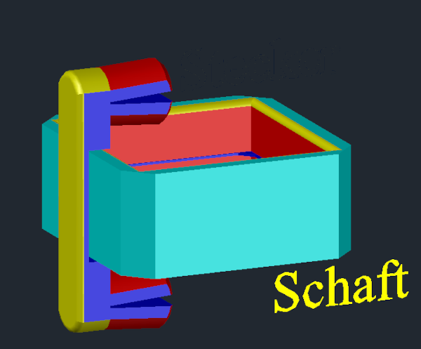
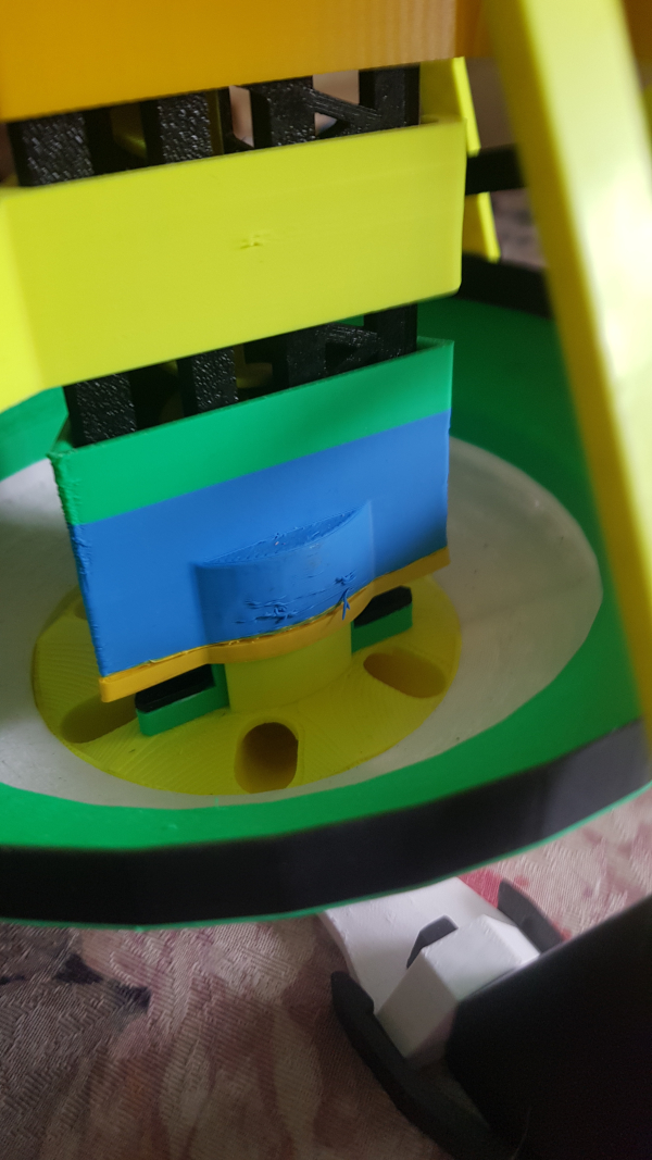
Before printing, increase the fill to 50% so that the strut brackets cannot break off when inserted.
First insert into the funnel bracket, then insert the lift strut on top.p>
It is pushed over the strut in the funnel holder for even better stabilization.
Therefore, have the strut ready when inserting, as it will not be possible later.
Horizontal pressure usually leads to more reworking with a file
and unsatisfactory results, as the part can bend.
We recommend vertical pressure with support, but only from the pressure plate.
This creates support arms at the top that prevent wobbling during printing.
to ensure smooth operation in the technical models.
The diameter is 9.6 mm.
No other balls that meet the requirements have been found to date.
“L-” means left-aligned, counterclockwise when viewed from above.
“R-” means right-aligned, clockwise when viewed from above.
For printing, it is recommended to place the part horizontally with the
ball ejection opening facing upwards on the print bed
and tilted at an angle of approximately 15°.
If you then activate the support structure only on the plate,
you will get the best results,
because the supports between the crossbars can reach the
opposite side wall.
This prevents balls from jumping out of the chute at discharge openings
such as funnels and other locations.
“X-” means regardless of the direction of travel.
Updated on May 26, 24.
SOUVENIRS:
KEY RING (stl)
(5 pieces)
As of: October 29, 2025
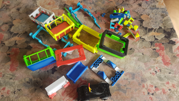
This is a result from the
initial phase of PeterPlus
and contains “childhood memories”
of a very popular toy...
/* Das popover kann ich hier schon angeben mit Inhalt
und dann an gegebener Stelle einsetzen*/
Does not protrude beyond the strut corner, suitable for lift struts with direct extensions on the outer wall.
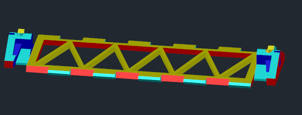
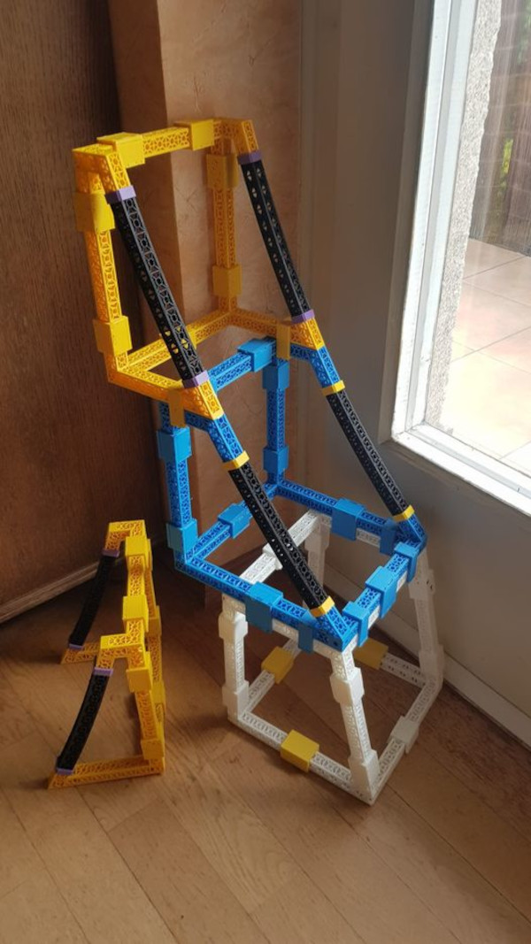
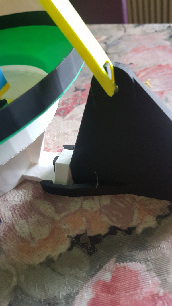
Triangle struts (stl)
As of: May 26, 2024
3-corner struts consist of 3 printed parts each,
arranged like an equilateral triangle and connected with small
“Y-claws” at the top and bottom.
In this form, they are very resilient and can be connected
to the next one with 3 “clips” each.
This allows long strut towers to be created,
which are of fundamental importance in larger models.
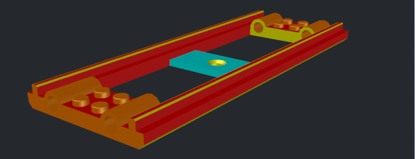
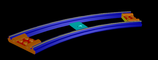
Used if a track runs through the strut of another model
and is thus also supported by it.
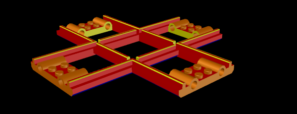
Used for storage and transport, providing a quick overview of inventory.
Joint nodes are track bed supports on a strut tower that allow for finer adjustments in distance and angle and consist of two parts each.
The “clamp” grips the “rod,” allowing one of the parts to be tilted in most cases.
Different shapes are available to accommodate all possible variations.
Since the correct setting can often only be determined on site,
screw-on spacers are also available.
They can also be used for joint extensions,
with the tower continuing above and the track passing through
the tower, so to speak, and perhaps crossing another track further up.
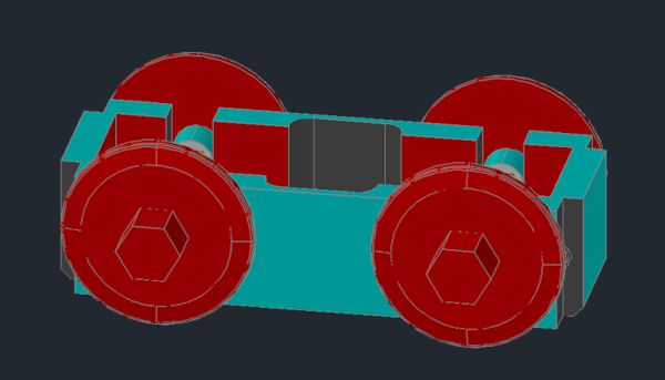
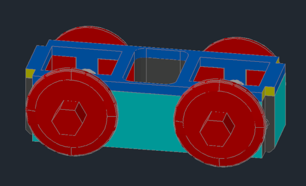
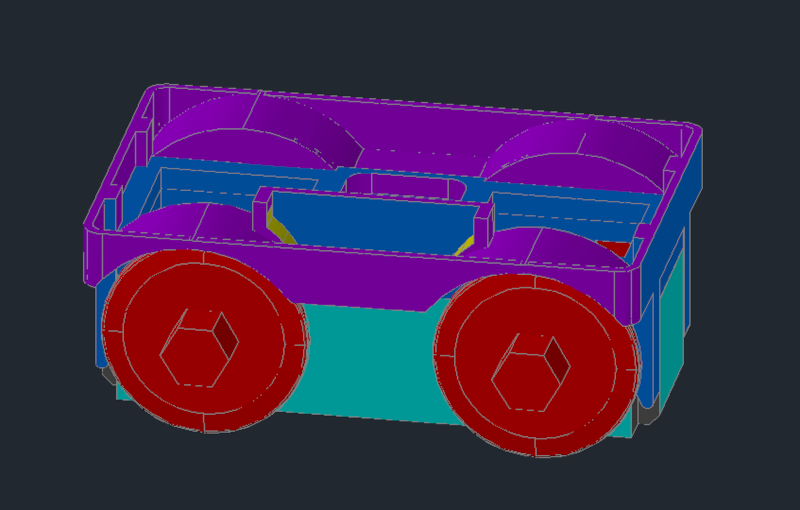
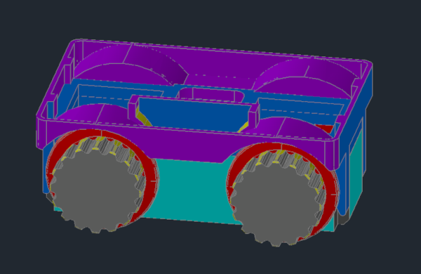
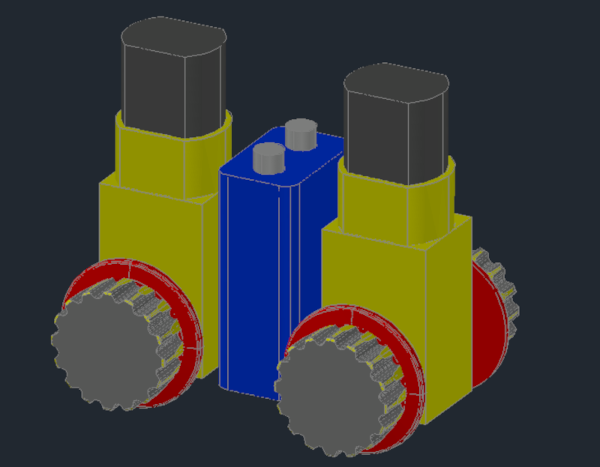
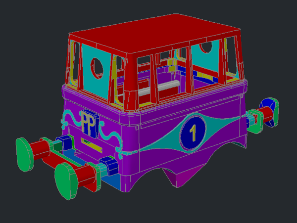
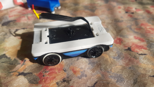
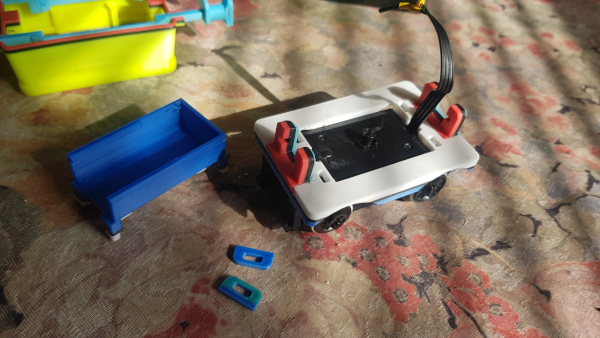
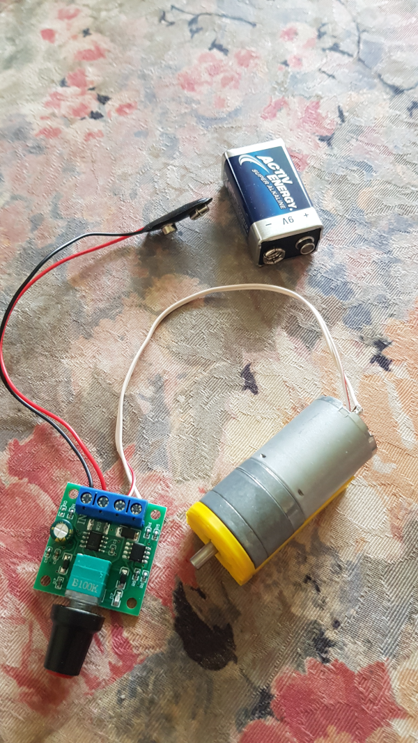
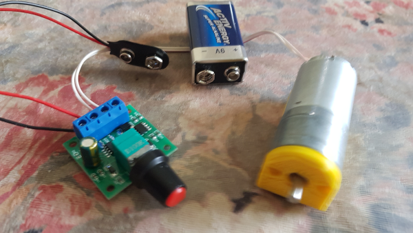
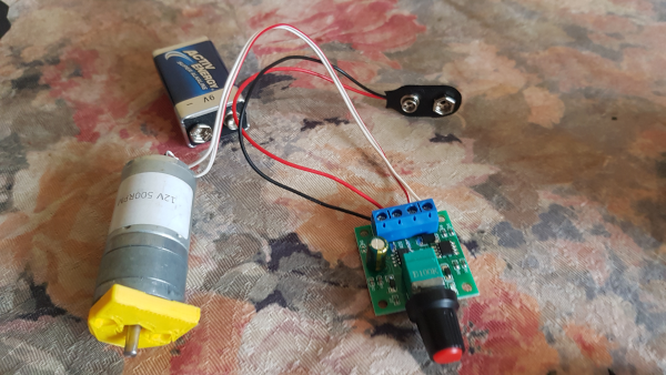
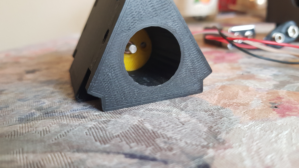
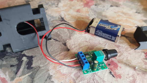
Created in fall 2023, when Heinz discovered a
new, powerful motor online that had direct wheel axles,
thus eliminating the need for a gear wheels gearbox:
8pcs DC3V-12V DC gear motor
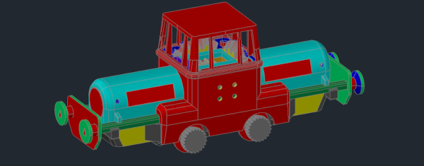
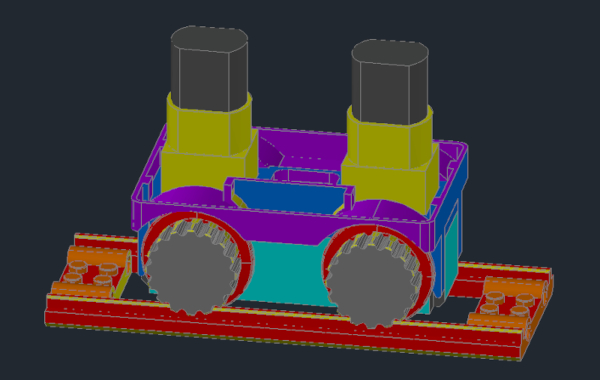
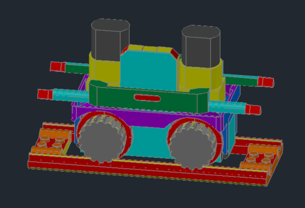
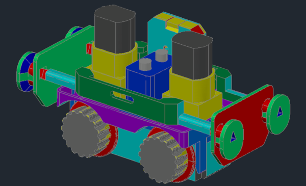
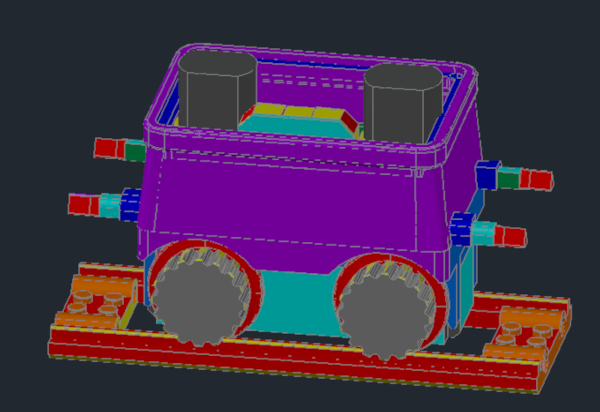
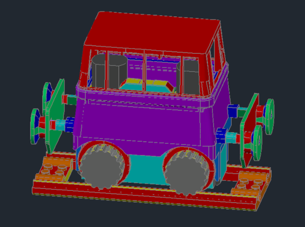
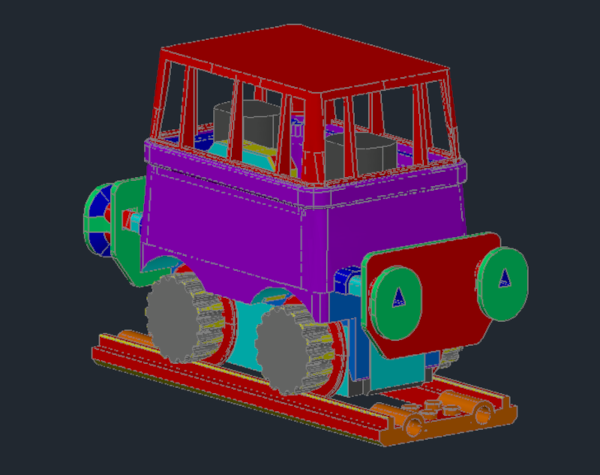
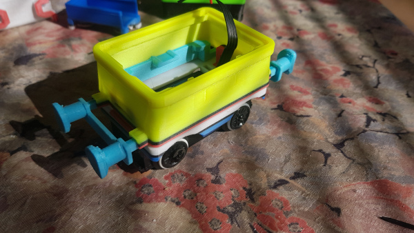
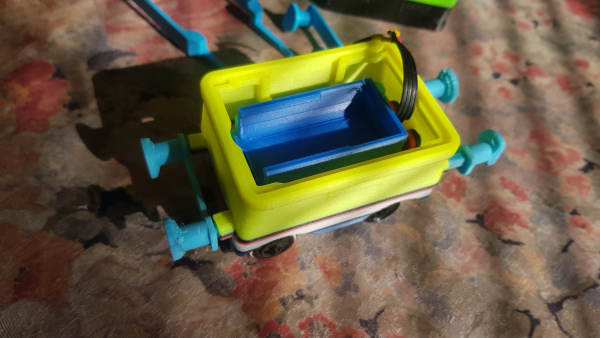
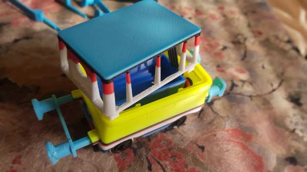
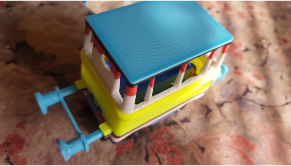
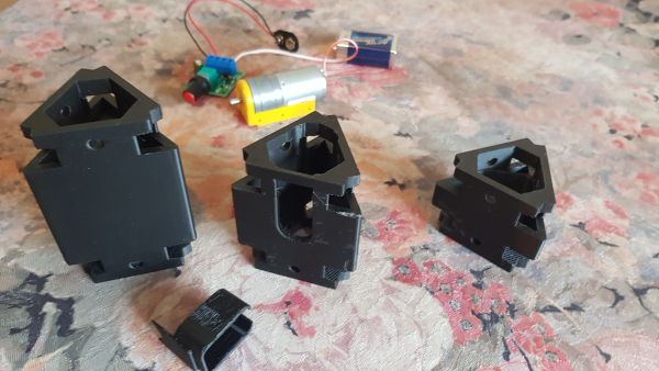
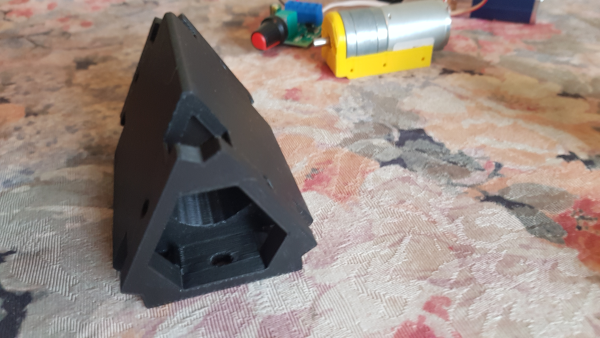
Locomotive 05 “Loc Nr 5” (stl)
(the last and most agile)
As of: October 11, 2025
The continuation and improvement is through
a motor with two axes corresponding to the
original Lego motors.
88002 Traction motor, black, 55g
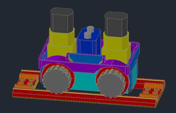
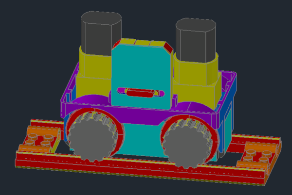
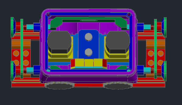
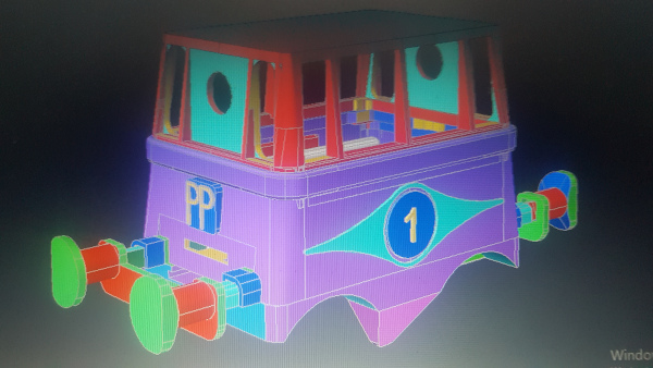
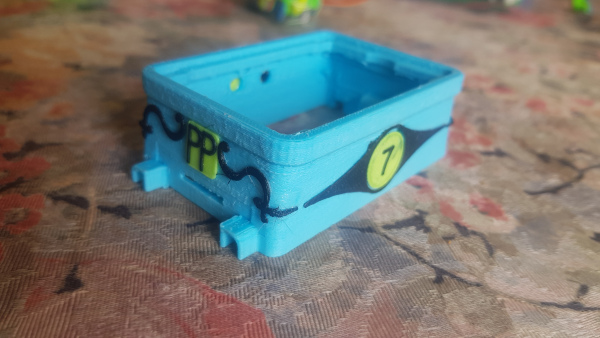
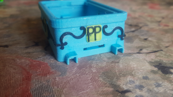
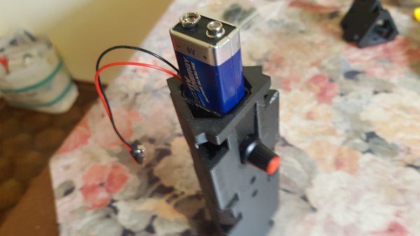
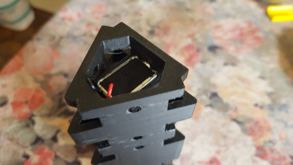
For the equivalent replica of our most frequently used locomotives,
including switch mechanism and adjustment control, here is a list of
sources for all individual parts found by Heinz:
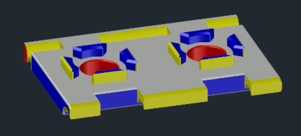
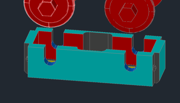
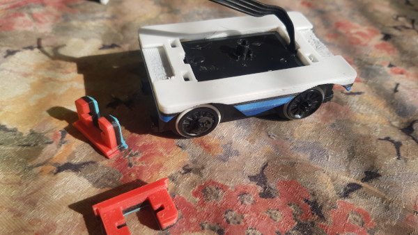
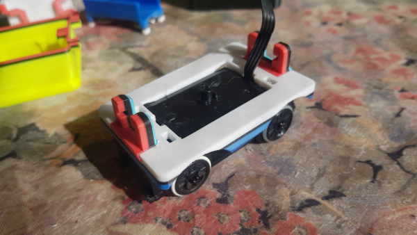
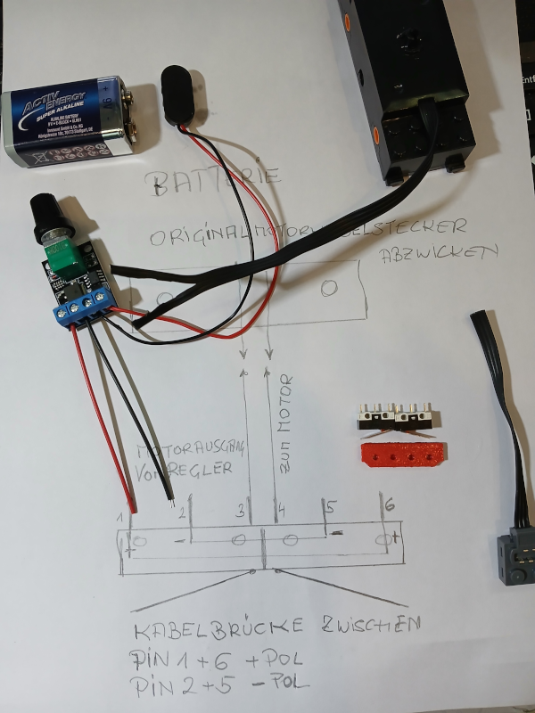
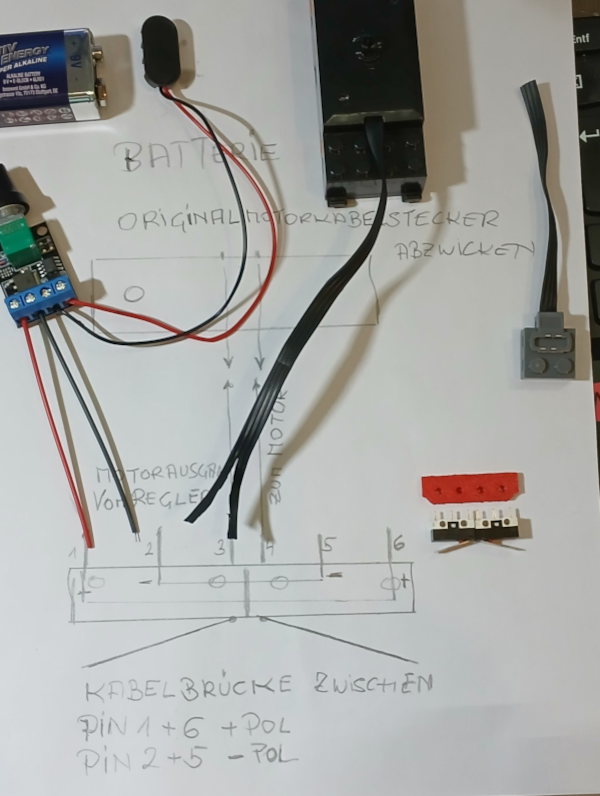
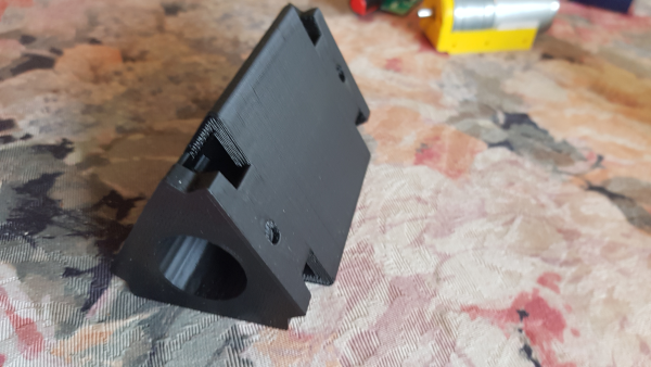
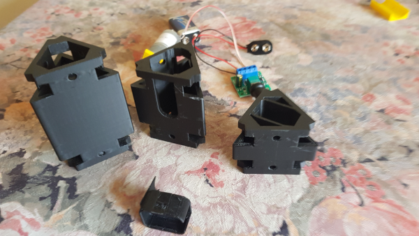
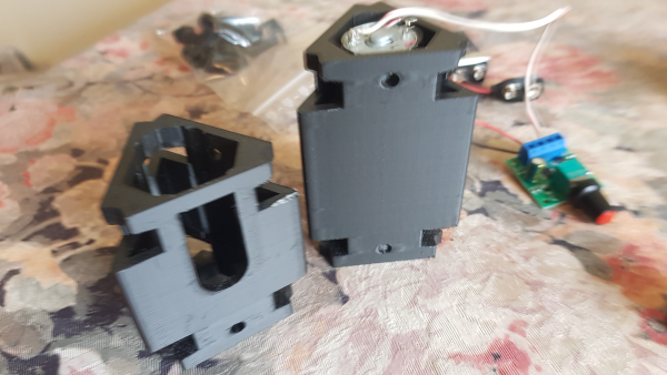
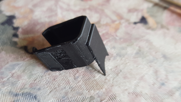
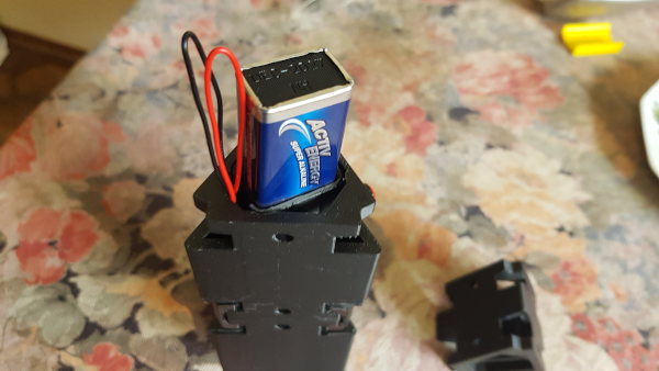
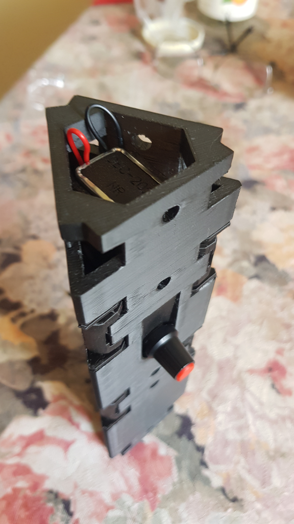
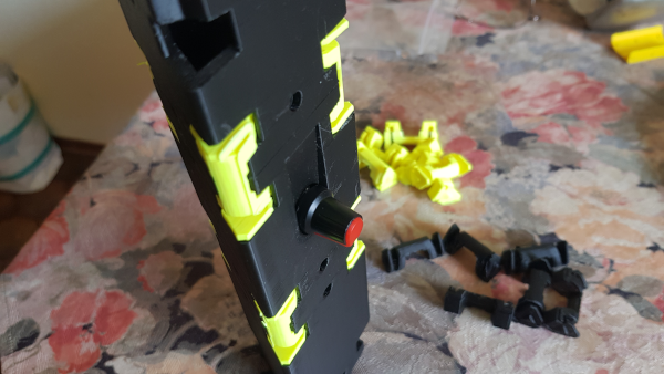
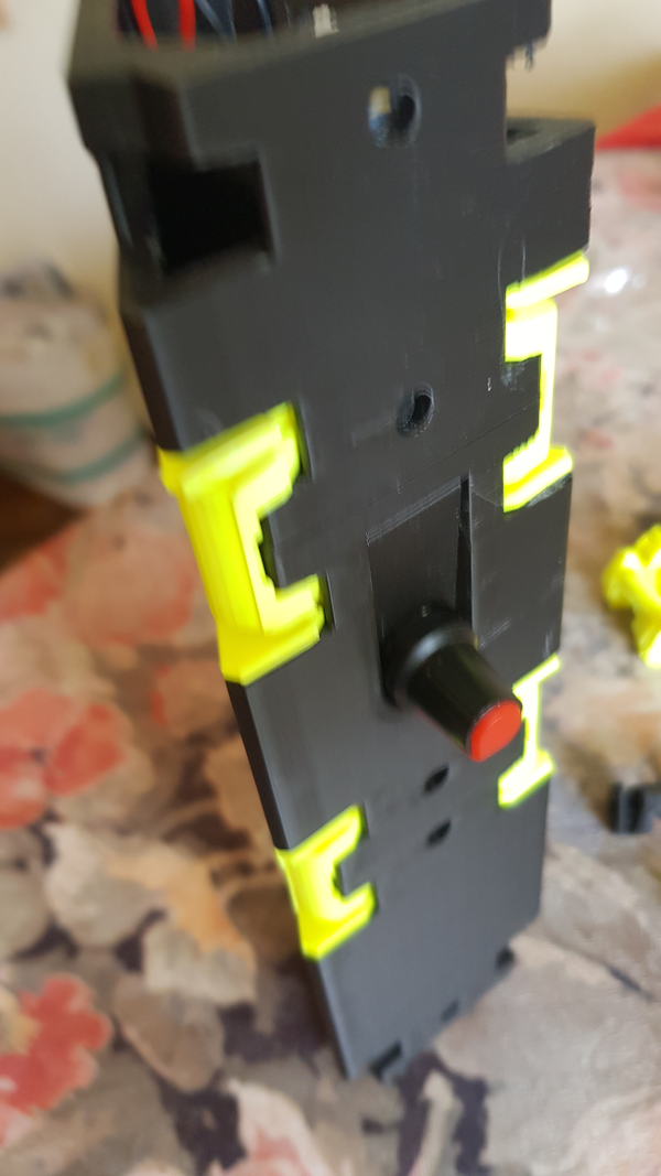
The two microswitches are glued to the red part,
the pressure part “Attachment 1 electrical plug.”
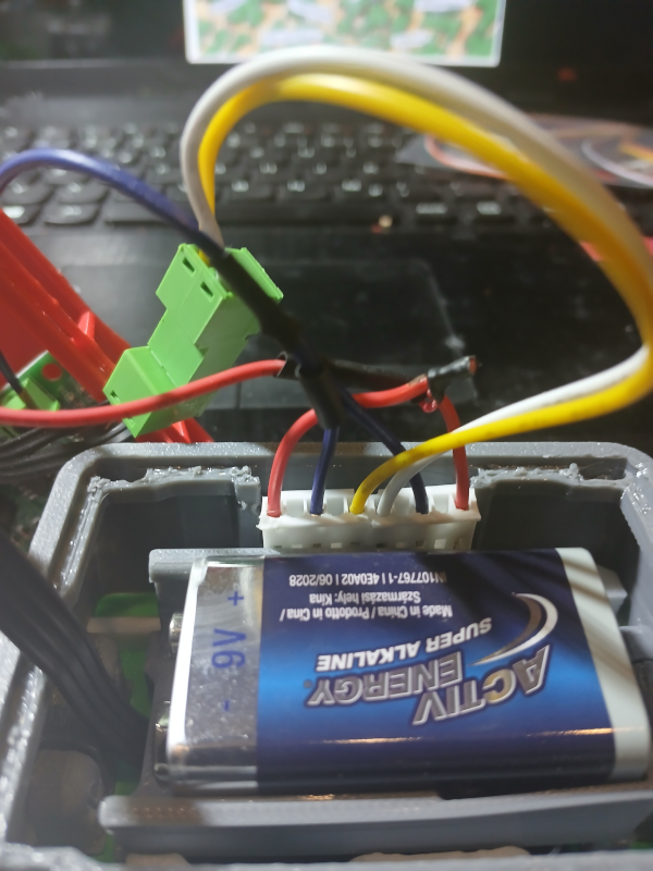
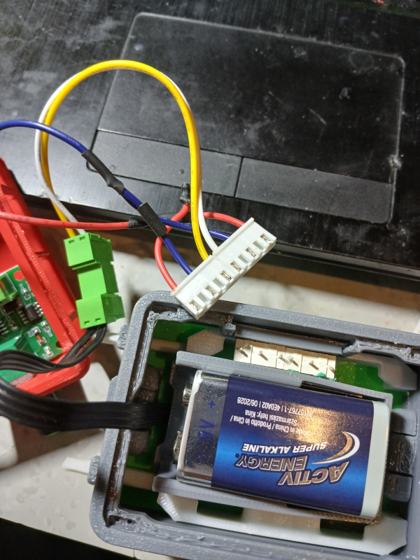
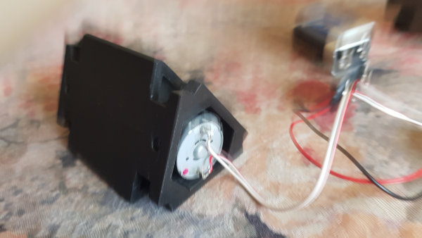
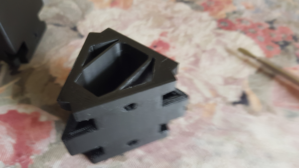
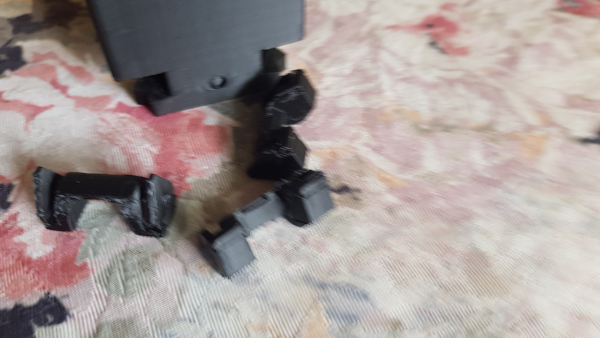
After soldering all components, it can be
easily inserted sideways into the locomotive frame
with the microswitches facing downwards.
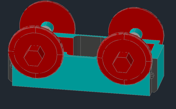
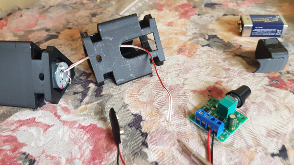
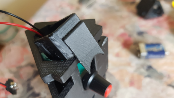
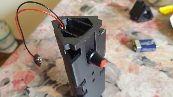
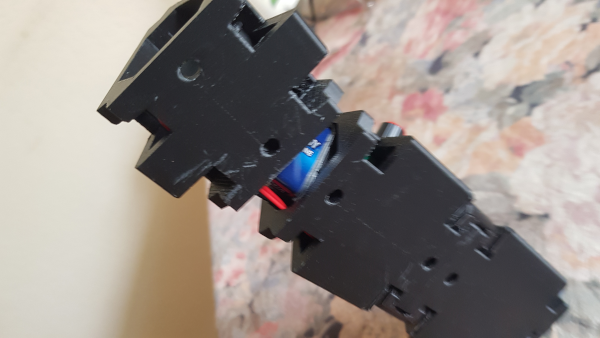
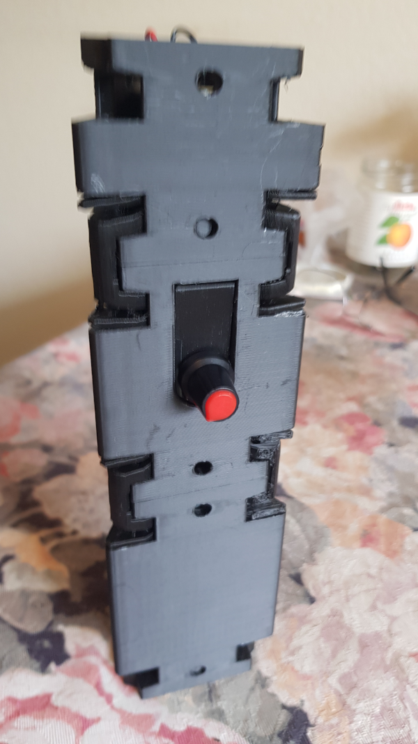
When assembled, moving the buffer rods to switch the direction of travel.
Buffer rod A must be on the switch side.
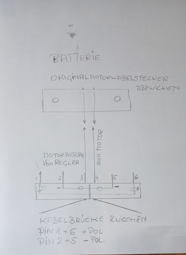
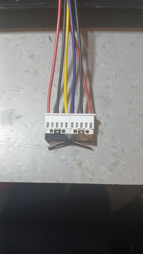
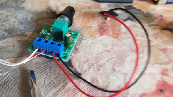
To simplify the connections of the switch even further,
cable sockets can also be used.
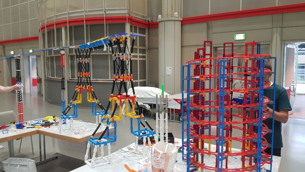
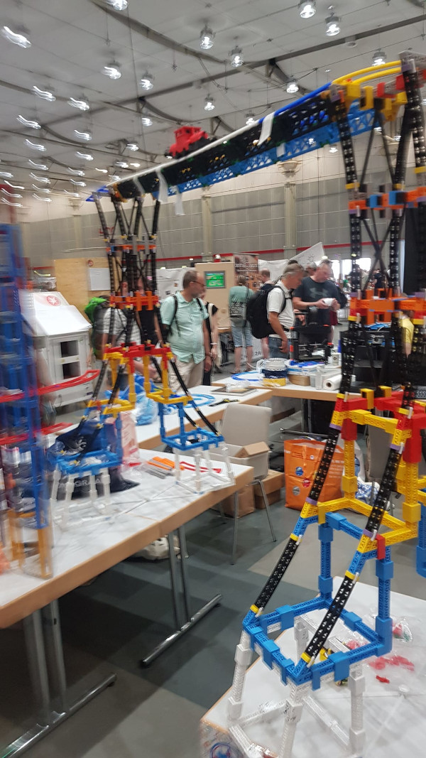
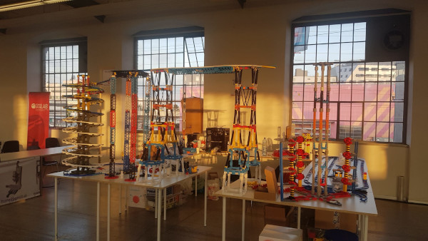
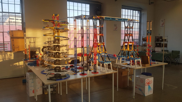
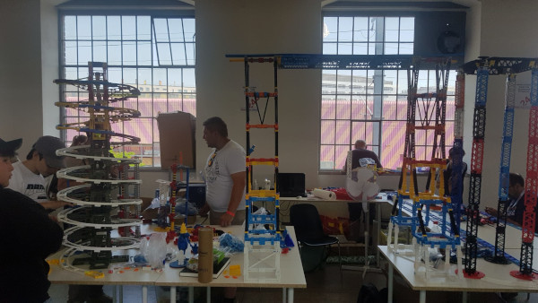
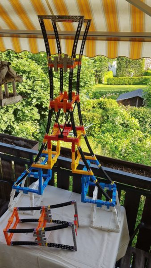
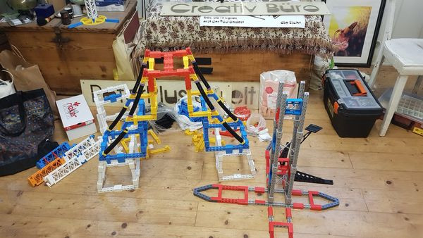
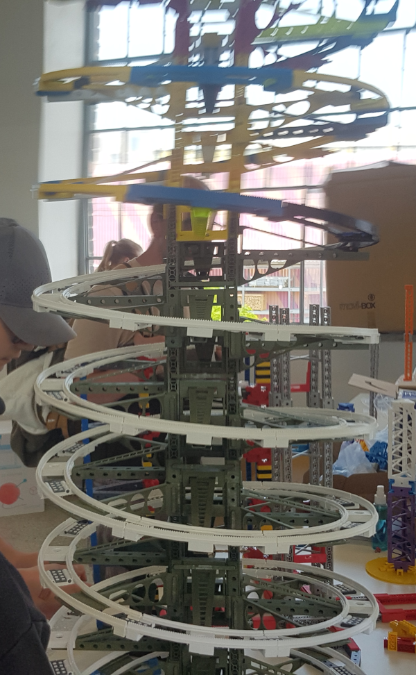
EIFFEL BRIDGE (stl)
(approx. 20x80x126cm)
As of: May 26, 2024
The bridge was built starting in March 2023 and consists of six levels per pillar
and the track structure above it.
Levels 1-3 are two-part and taper to one at the top.
The bridge currently consists of at least two pillars; the number of parts to be printed
is indicated in the name suffix and refers to only one pillar.
Additions such as connecting clamps and other items are also specified
with the number to be printed per level according to the photos.
The files for levels 1-6 are offered in 6 groups as zip files, or as a whole.
For example, parts C and D of level 1 correspond to Strut 6, which is often used
for other purposes and is also found in the other levels.
Parts C and D of level 1, for example, correspond to BRACE 6, which is often used
for other purposes and also appears in the other levels, as does BRACE 7.
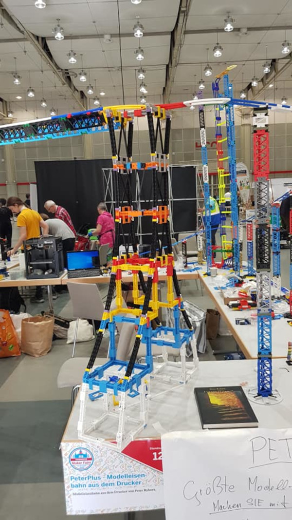
The X- and V-shaped struts in levels 4-6 serve to stabilize
and can only be seen in photos. They are attached on both sides on top of each other on the
flat side of the pillar: E4: V, E5: X, E6: A (V inverted).
The corresponding fixing flaps are specified separately in the accessories
so that they can be printed in a common color if desired.
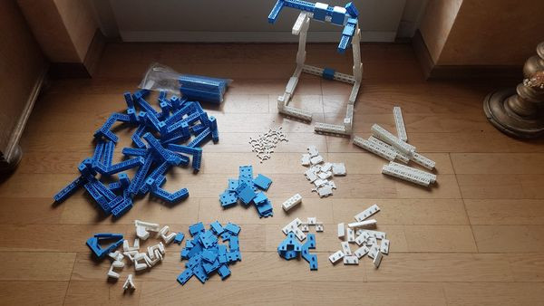
EIFFEL BRIDGE ACCESSORIES (stl)
Connecting elements, reinforcements
As of: May 26, 2024
If you want to print the correct number of fixing flaps in different colors
for each level according to the photos and the original:
(Levels 1-3 are two-piece, therefore more fixing flaps, levels 4-6 are one-piece)
Fixing flaps for the side V and X struts:
2x2: 32x / 2x4: 16x / 2x8: 16x
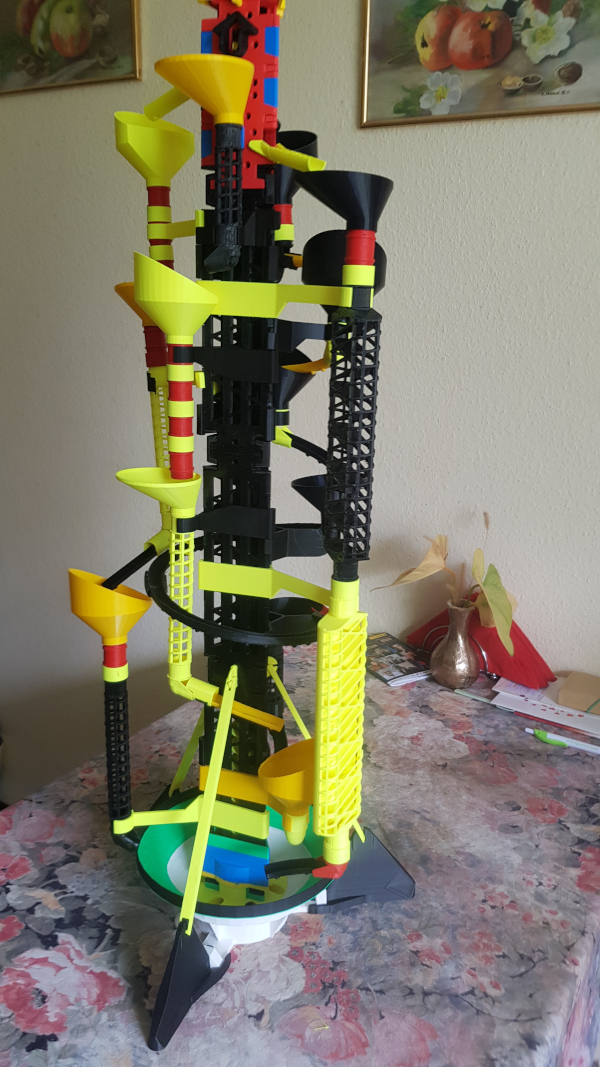
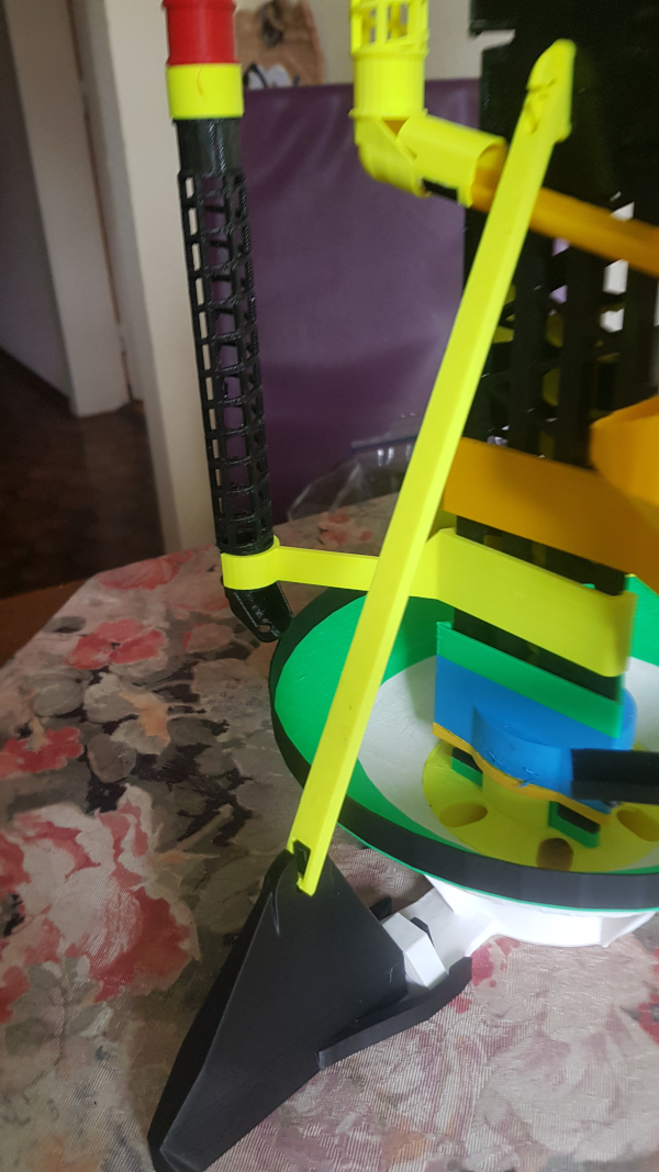
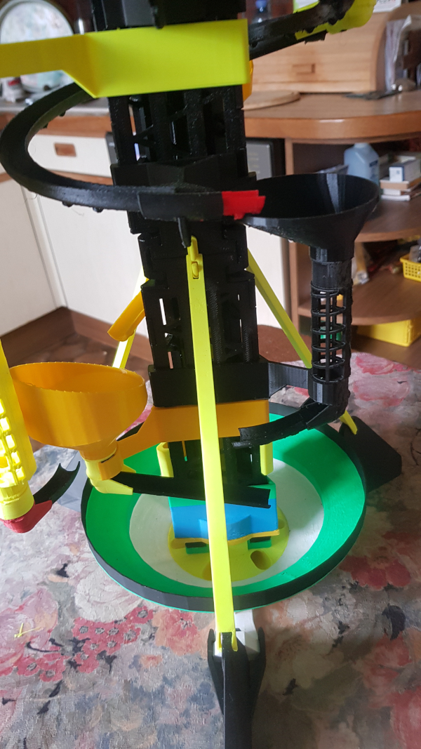
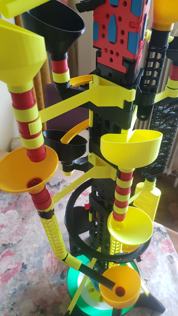
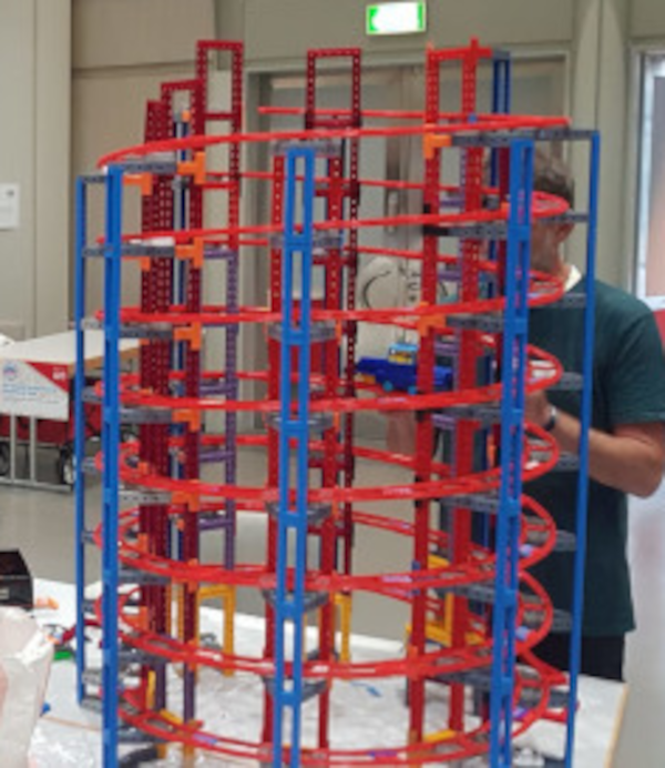
BALL LIFT TOWER (stl)
(Height about 1m)
As of: May 26, 2024
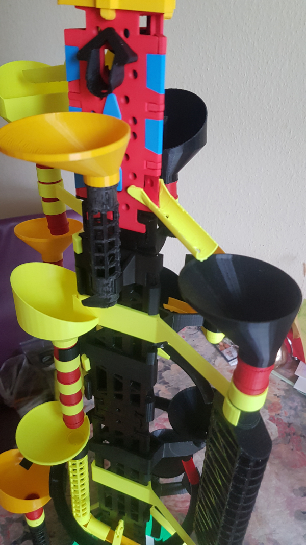
The lift tower is shaped like a strut with a rotating spiral inside it.
a rotating spiral. This transports the balls like an elevator
up six shafts, and each shaft can have its
ball ejection opening at a different height and guide the balls into
different ball paths.
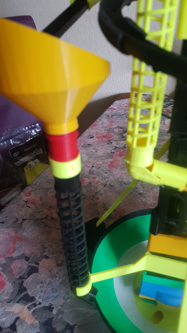
BALL LIFT TOWER ACCESSORIES 1 (stl)
Ball tracks, funnels, chutes, etc.
As of: May 26, 2024
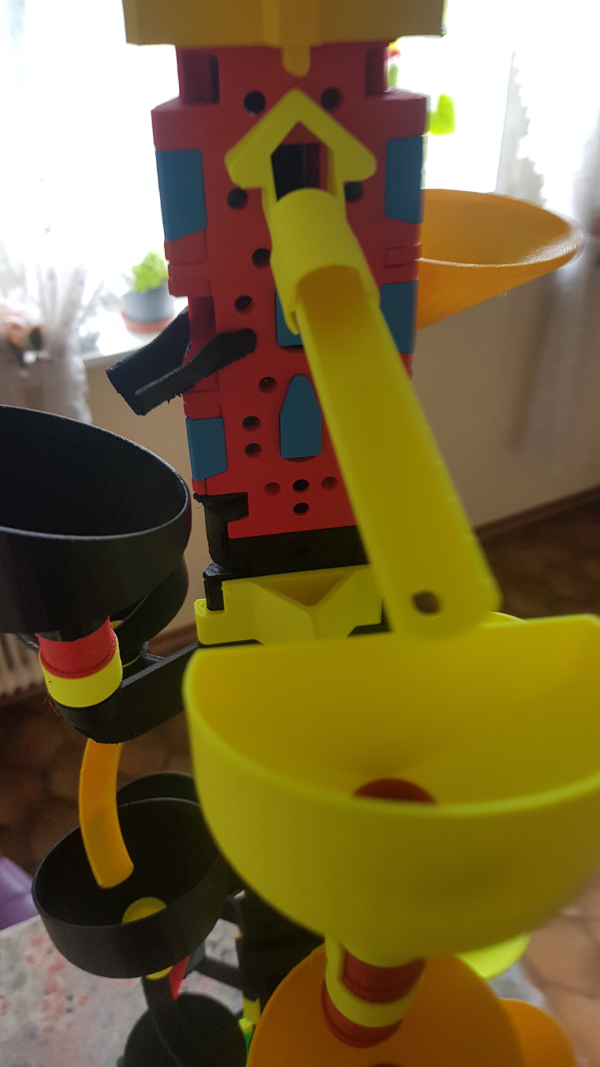
The selection of accessories offers endless variations of marble runs.
To make it easier to get an overview, I recommend first designing a simple track
and printing the parts you have selected for it.
Gradually, you will understand more and more of the individual parts that are required
to design the tracks exactly as you want them.
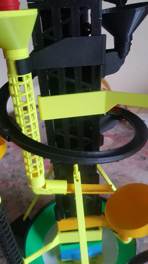
In this example, only 4 of the 6 available lift shafts are open.
Theoretically, you only need one open one, but it must be at the top,
otherwise there will be a traffic jam. This is because the middle spiral transports the
balls counterclockwise from shaft to shaft at the end
until they can exit, but not downwards.
That is why there must always be an open hole at the top.
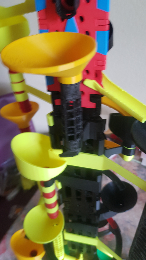
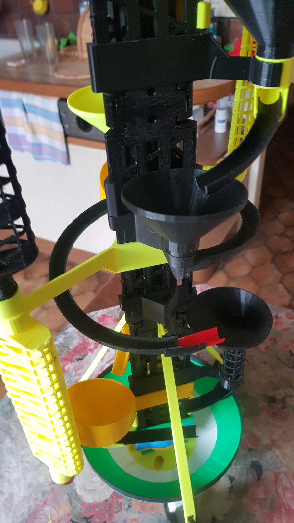
BALL LIFT TOWER ACCESSORIES 2 (stl)
Ball tracks, funnels, chutes, etc.
As of: May 26, 2024
The second part also deals with ball spirals, but these can be placed on
separate towers next to the ball lift,
as well as other possible connections and ball chutes for them
in various shapes.